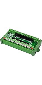
🔧 Elevate Your Raspberry Pi Experience!
The HCDC RPi GPIO Status LED & Terminal Block Breakout Board HAT is a fully assembled module designed for Raspberry Pi models A+, 3A+, B+, 2B, 3B, 3B+, and 4B. It features intuitive LED indicators for GPIO status, a versatile terminal block for various wire sizes, and a low power consumption design, making it an essential tool for any Raspberry Pi enthusiast.
D**G
Easy way to test code.
This provides a light for every output, plus access to the output with a screw terminal rather than having to make a header for connection. It is a step closer to installation in the final product without the need for weaker connection means, plug in socket with a wire is not a reliable way to implement a project. With this, you can test outputs by sight, and simulate inputs with simple means. Well worth the money. After the first arrived, I ordered three more.
A**R
Easy to use
Way better than using the pins
E**K
Well built non-intrusive connections and monitoring for your GPIO pins
Since Amazon likes to combine reviews for totally different products, this review is for the HCDC RPi GPIO Status LED & Terminal Block Breakout Board HAT. I'm not sure why people complained about putting this board in a case. It is pretty obvious that many HATs will not fit inside a closed case. This board will work with a male to female 40-pin flat extender cable if you remove the two plastic posts on either side of the connector. You really don't need those posts except to permanently attach it to the base board or another HAT. The connector works pretty well as a "foot" and you can leave the other posts for feet on the other side. I am using a Compute Module 4 with a WaveShare IO baseboard. This has plenty of clearance above the Waveshare heat sink and Compute Module 4. Although I can't close the case, I could file a slot in the cover and use a ribbon cable.My only minor complaint is that the signal designations on the terminal blocks are ordered differently than for the connector pins. I haven't figured out if there is a system to it, but they seem quite random. In some cases the label is the GPIO pin and in some cases it is the usual function, like "TX' or "RX". Probably it wasn't possible (or easy) to make a layout on the terminal blocks to match the connector pin ordering. With a little bit of care in finding the right connection, this provides all the signals.What impressed me was the construction. If this is built by hand, it was done very well. There were no cold solder joints, splashes or burnt lands from using too much heat. It actually looks like it was put through a wave soldering or surface mount soldering machine. The plastic posts could have been metal, but they're good enough being plastic.For the price, this board is a good value. I'm porting an OS to the Compute Module 4, and this board has saved me from hanging LEDs off of my board. It is also nice to see the serial port TX and RX data to at least know of the signals are reversed (one LED on instead of 2).
R**W
excellent GPIO breakout board
This is an excellent little GPIO breakout board you can attach to your pi 4. Arrived fast. Packaged okay.. to be honest the packaging was all torn up and I was surprised it wasn't broken in shipping but it worked. It's hard to actually damage an item like this I think unless you overdrive it. I attached it to my pi and an Adafruit 240x240 LCD display then wrote a matrix style screen saver in python and it works flawlessly. I think I read it had led's in the amazon description, but seeing it's leds light up looks great and is actually educational. I bought this one for my pi 4 dev machine and am so impressed I will likely buy a couple more for other pi 4s I use in python automation code development. I couldn't be happier with purchase. Highly recommend if you're into things like this.
E**Z
It works really well but has a couple of confusing eleiments to it
It functions fine and does exactly what it suppose to do which earns it 5-stars.BUT, I found two aspects to it to be confusing:1) The terminal connections don't have any correlation to the 40-pin connector & LED layout on the right side. You can have pin 1 located on the 3rd row of terminal connections and pin two can be on the 1st row, pin 3 next to it and pin 4 on the 4th row. Very confusing.2) The led indicator lights for the GPIO connections turn on when the circuit is Open and turn off when the circuit is Closed. Like turning a switch off to make the like turn on and vice versa.Otherwise, it works fine once you understand its quirks.
Trustpilot
2 weeks ago
3 days ago